Prior to the widespread integration of CAD systems in the 1980’s part drawings were filled with leader lines to features delineated by dimensions for size and location with independent tolerances. CAD systems have made the designing of parts both better and quicker and have a positive impact downstream from product design. Also known as Digital Product Definition (DPD) the MBD revolution in design has had both good and bad repercussions for the foundry industry.
O’Fallon Casting has been at the industry forefront in adopting technologies that support Model Based Definition designs. OFC can tool, manufacture and inspect its manufactured castings to a customer solid model without the need of a 2D drawing.
OFC Customers have varying degrees of MBD implementation. Some provide a solid model with a fully dimensioned drawings others with partially dimensioned and sometimes with drawings that contain no dimensions whatsoever. O’Fallon Casting has found that limited dimension drawings, especially for larger sizes of castings, are an effective way for an engineer to convey information regarding the important features of a part design.
Model Based Definition has helped reduce the cycle time from receipt of a design to the shipment of product. Toolmaking has become faster and more accurate as has the inspection of first articles. The First Pass Yield of MBD parts is better than it is for castings from tooling manufactured from fully dimensioned drawings.
The manufacture of Rapid Prototyping has greatly expanded with the advent of CAD solid model files. As the use of rapid prototypes has increased the materials, processes and equipment to produce them has also improved. Additive manufactured patterns from SLA, SLS or Voxeljet technologies are used to produce 1-off quantities or even low rates of production directly from a customer CAD file. (It should be noted, however, to successfully manufacture rapid prototypes the supplied CAD solid models must be complete with fillet radii; a detail that is frequently omitted by engineers because of the modeling time required and size of the resultant files.)
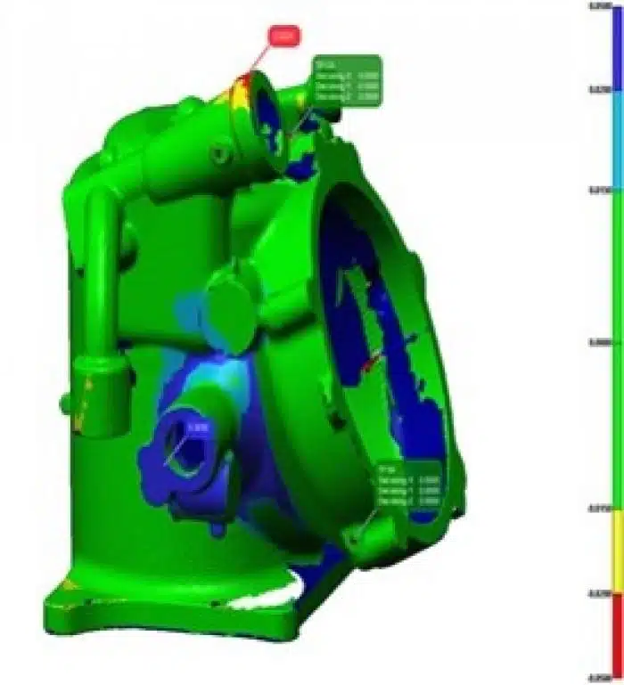
Laser scanning inspection of castings to their Solid Models is both less expensive and more informative as compared to the normal inspection of a fully dimensioned drawing. Traditionally the inspection of a part surface to a dimensioned drawing is made by the measurement of a series of points along the surface. By comparison a laser scan accumulates millions of points per square inch and so is capable of detecting small variations in the surface that would remain undetected by a traditional “point” methods. The wealth of data from a laser scan makes the dimensional analysis of a casting better and aids the ability of an engineer to discern in-process deviations from tooling errors.
The variety of available CAD formats can be challenging to a supply chain especially among smaller subcontractors. Parasolid (.x_t) and Step (.stp) file formats are generally well supported across the industry. Iges (.igs) files can be universally read but can be difficult to use as they seem to be very prone to file errors. Formats other than Parasolid, Step or Iges are likely to be translated to a locally readable format at some point along the supply chain. The use of other than the generally excepted CAD formats can also serve to limit the number of available subcontractors and may increase the cost for services.
More the case in the past, but still true today, Document and Data control of MPD CAD files has been found to be “difficult”. Part drawings and associated CAD files can sometimes go out of “sync” with each other and obsolete revision files have been mistakenly distributed. As a result of bad experiences some customers have become reticent to supply their CAD files for fear they are not up-to-date.
Tooling subcontractors, however, have become dependent on their receiving a customer solid model for their design and manufacture of tooling. Without a supplied customer CAD file it often becomes necessary for a toolmaker to first create their own Solid Model of the part. This extra step adds time and expense to the procurement of the tool and any latent errors found in toolmaker developed CAD file can also contribute to delays in product deliveries.
Model based definition products have become the norm in the investment casting industry. MBD possesses advantages in speed and accuracy of a designed product that far outweigh the challenges to downstream users of the files.
O’Fallon Casting is very familiar with the manufacture of nonferrous investment castings to their CAD solid models. If you have any questions regarding Model Based Definition please contact your O’Fallon Casting Sales Engineer.
